|
When the fuse holder block is in the ON position, and House power source breaker is ON, power is connected to the machine.
Connecting Compressed Air. Compressed air is used to activate pneumatic components of the machine. There are two components activated by pneumatics. Press Cylinders (2) and Die Release Cylinders (4). All cylinders for this machine were specified as high temperature cylinders which mean they are rated to work with operating temperatures up to 500 deg F.
Prior to connecting compressed air, please make sure that your compressor can provide a constant supply of 80 to 90 psi of DRY air pressure. Also prior to installing compressed air, make sure that all packing straps, materials used for packing the Custom Pouch Sealer are free of the machine. The location of the air compressor as it regards location of machine doesn’t matter as long as air pressure/volume is available to machine.
 |
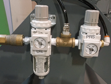
Pneumatic Inlet & Gauges Section is shown in the photo (above) and is located on the opposite end of Control Panel. Connect your compressor air hose with quick disconnect to incoming end of Air Filter/Die Regulator. The Air Filter will capture any water/moisture in your compressed air line. Make sure to remove any water buildup in this reservoir. Parts Replacement Warranty on air cylinders is voided if water or moisture is found in any air cylinder. Therefore it is very important that Air Filter reservoir is checked regularly. If you notice an accumulation of water more frequently than preferred, we recommend you add a water/moisture extractor, dryer or timed water release valve to your air compressor. Contact Novaseal for details of various accessory products recommended for this machine. To remove water accumulation from the reservoir, disconnect the compressed incoming air line and unscrew reservoir to remove water accumulation.
As soon as compressed air is connected to the machine, a couple of things will happen. Firstly the Upper Die structure will move to UP position. Die release cylinders are normally engaged, and can only be retracted by selecting command on PLC/HMI.
Prior to modifying air pressure, wait for your air compressor to properly supply compressed air to each Air Regulator. Factory Default Settings for each Air Regulator/Gauge.
- Upper Die Press, PRS = 30 psi
- Die Release, DIE = 45-50 psi
For best results compressed air should always be connected to Custom Pouch Sealer. If necessary, air regulator pressure can be adjusted by gently lifting regulator cap and turning clockwise to increase pressure or counterclockwise to decrease pressure. Air regulators are cascaded which means that full pressure goes to first regulator, in this case, the Die Release, and less pressure goes tot second regulator, Upper Die Press.
Cleaning the Machine. This machine is a sophisticated high tech heat sealing machine and debris left on the machine can and will adversely affect the quality of the seal or possibly cause other non-desirable results. Aside from general cleaning and maintenance of the Custom Pouch Sealer, please make sure to remove any sealed material that may adhere to bottom of upper die or top of lower die. When cleaning smooth painted surfaces, clean with Formula 409 (or equivalent) spray cleaner.

|