|
We suggest you use a State certified electrician to connect the electrical power source. Note that Line 1 and Line 2 are fused, and that Ground Line is not fused. Pre-installed 30 Amp Amp fuses are delay type fuses. Although the machine draws significantly less than 30 Amps, we recommend using 30 Amp Time Delay Fuses if and when fuses need to be replaced.
If you ever need to replace or remove fuses, make sure that the main circuit power source providing power to the Safety Switch is in the OFF position before replacing fuses.
Once electricity is connected, close the Safety Switch enclosure. Turn on your main circuit breaker power source and assure electricity is flowing from your circuit breaker panel to the machine. Next turn the Safety Switch on by moving the side Handle Lever to the UP or ON position. You now have power going to the machine. .
Do not power on the machine prior to connecting compressed air.
Connecting Compressed Air. Compressed air is used to activate pneumatic components of the machine. These components include main sealing components Upper Sealing Bar (Press) and Rockers; as well as custom components including Rear Clamp Bar, Pre-Press Clamp Bar, and Flipper.
Prior to connecting compressed air, please make sure that your compressor can provide a constant supply of 90 to 100 psi of DRY air pressure. The location of the air compressor as it regards location of machine doesn’t matter as long as air pressure/volume is available to the machine.
 |
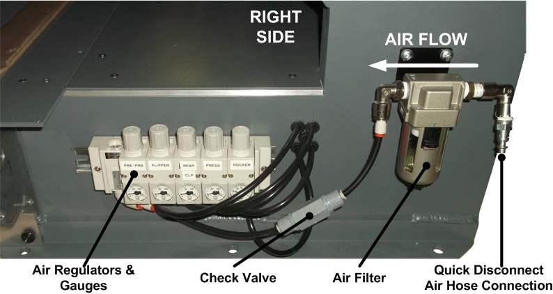
Pneumatic Inlet & Gauges Section is shown in the photo (above) and is located on the right side of the TableTop PulseSealer, below the machine Table. Connect your compressor air hose with quick disconnect to the incoming end of the Air Filter. The Air Filter will capture any water/moisture in your compressed air line. Make sure to remove any water buildup in this reservoir. Parts Replacement Warranty on air cylinders is void if water or moisture is found in any air cylinder. Therefore it is very important that Air Filter is checked regularly. If you notice an accumulation of water, we suggest you add a water/moisture extractor, dryer or timed water release valve to your air compressor. Contact Novaseal for details of various accessory products. If you begin to see liquid level rise, disconnect the compressed air line from the Air Filter and empty the Filter reservoir.
As soon as compressed air is connected to the machine, a couple of things will happen immediately. First, the Upper Sealing Bar will move to the upper position. Second, the Rockers will activate and maintain pressure on the pre-installed Heating Elements. Additionally, the Rear Clamp Bar will move to upper position; and Pre-Press Clamp Bar will move to upper position. Slight movement may also occur in the Flipper. Both Rear Clamp Bar and Pre-Press Clamp Bar may still have enough compressed air inside of the lines not to notice much of a upward movement. How much movement depends on how much air escaped during machine transportation.
To the left of the Air Filter is the Pneumatic Pressure Regulators and Gauges. Connected between the Air Filter and Regulator/Gauges is a Check Valve. Check Valve holds onto pressured air for up to 2 to 3 days, and will keep the machine pressured during a weekend or a short time of non-use. Continuous air pressured on Heating Elements keeps the Heating Elements in good condition. There are 5 Regulator/Gauges.
Factory Default Settings for each Air Regulator/Gauge:
- ROCKER = 34 to 38 psi (plus/minus 1 psi)
- UPPER SEALING BAR (PRESS) = *35 psi
- REAR CLAMP BAR (REAR CLP) = *15 psi
- FLIPPER = *20 psi
- PRE-PRESS CLAMP BAR (PRE-PRS) = *20 psi
Please note that asterisked *Factory Default settings were the last settings used when testing your compressible boards. Additional Regulators/Gauges were provided so that you are able to modify compression pressure for each board thickness and allowable compression. For example, more compression on styrofoam core boards, less on foam boards. Rocker pressure should remain constant for each heating element width. On 1/4-inch widths, use 34 psi. On 1-inch widths, use 36 to 38 psi. Too much or too little Rocker pressure will result in premature Heating Element failure. Note that sealing pressure can be modified two ways ... air pressure, and Upper Sealing Bar cylinder stroke length adjustment.
Allow a few minutes for your air compressor to properly supply compressed air to each of the Air Regulators, then compare Gauge values with Factory Default Settings. If Air Regulator values differ, please reset values as shown above, at least for the first test of the machine. To change an Air Regulator pressure value, gently lift the knob on top of the Air Regulator, turn knob clockwise to increase air pressure or counterclockwise to decrease air pressure. Once set, gently push knob down which locks the air pressure value setting.
Cleaning the Machine. Prior to shipping the TableTop PulseSealer machine, all debris was removed or cleaned from the machine. The TableTop PulseSealer is a sophisticated high tech heat sealing machine and debris left on the machine can and will adversely affect the quality of the seal or possibly cause other non-desirable results. For smooth painted surfaces, clean with Formula 409 (or equivalent) spray cleaner. When replacing Heating Elements, we recommend using DeoxIT to assure electrodes are free of oxidation. Oxidation buildup can dramatically reduce Heating Element life.
|